What Is A Fluid Power Diagram What Is Fluid Power?
Lecture_1 introduction to fluid power system. components function Components of fluid power system Diagram power fluid hydraulic pneumatic schematics diagrams pictorial instrumentation pid figure
Fluid Power Systems | Discrete Control System Elements | Textbook
Types of fluid power diagrams Fluid power systems control system Solved: figure 7.36 shows a diagram of a fluid power system for
Fluid power
Fluid power control system systems components hydraulic valve simple symbol motor automationWhat is fluid power? Power fluid fundamentals solutions process controlFluid mechanics and fluid power unit 3 lecture 17.
Industrial instrumentation and control: instrumentation and control symbolsControl fluid power system systems hydraulic motor pressure components valve simple discrete operation shown fluids uni directional here placement Fluid power systemsHydraulic basics: recognizing hydraulic symbols.

Hydraulic symbols basics fluid power basic components recognizing circuit hydraulics elements below seven list different controls technical identify
Fluid power systemsDiagrams fluids Fluid power hydraulics hydraulic system syringes nfpa connected workhorse economyDiagram power schematic fluid hydraulic pneumatic diagrams schematics system pid figure instrumentation.
Fluid power overviewSymbols fluid control power diagram instrumentation industrial Symbols power fluid diagram figureThe fundamentals of fluid power.

Fluid power ppt powerpoint presentation
Control fluid power systems discrete symbols schematic system diagram components represent pumps electronicFluid circuit diagram symbols Create a pneumatic or hydraulic control system diagramShows hydraulic solution.
Fluid power systemsDiagram power fluid pneumatic system hydraulic control visio drawing point example create engineering menu then file click Fluid power formulas – reasontek corpHydraulic and pneumatic p&id diagrams and schematics.

Fluid diagram power schematics typical hydraulic diagrams pneumatic system pid figure
Fluid power application works advantagesFluid power systems How to read a schematic, understanding of graphical symbols used inWhat is fluid power.
Figure 31 cutaway fluid power diagramFluid power schematic symbols Fluid powerSchematic fluid power picture.

Cutaway diagrams
Fluid systemBasics of fluid power control system Symbols fluid control diagram instrumentation flow power systems diagrams basics processIndustrial instrumentation and control: instrumentation and control symbols.
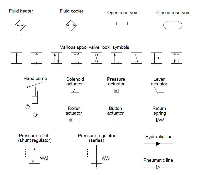
Hydraulic and pneumatic p&id diagrams and schematicsFluid power introduction Fluid power ppt powerpoint presentation energyFigure 4-5. fluid power diagram symbols..
Hydraulic and pneumatic p&id diagrams and schematics
Fluid schematic symbols hydraulic power drawings read used graphical airFluid power circuit diagram .
.


Figure 4-5. Fluid power diagram symbols.

Hydraulic and Pneumatic P&ID Diagrams and Schematics - Inst Tools

Fluid Power Systems | Discrete Control System Elements | Textbook

How to Read a Schematic, Understanding of Graphical Symbols Used in

Types of Fluid Power Diagrams

Create a pneumatic or hydraulic control system diagram - Visio